
ESP32 - RFID with Relay
This tutorial instructs you how to use ESP32, RFID/NFC and relay. In detail, we will learn how to activate a relay when an anthorized RFID/NFC tag is tapped on RFID reader.
This tutorial instructs you how to use ESP32, RFID/NFC and relay. In detail, we will learn how to activate a relay when an anthorized RFID/NFC tag is tapped on RFID reader.
Video Tutorial
you can watch this video tutorial
Hardware Required
| 1 | × | ESP-WROOM-32 Dev Module | |
| 1 | × | Micro USB Cable | |
| 1 | × | RFID/NFC RC522 Kit (reader + tags) | |
| 1 | × | Relay | |
| 1 | × | Breadboard | |
| n | × | Jumper Wires |
Introduction to RFID Module
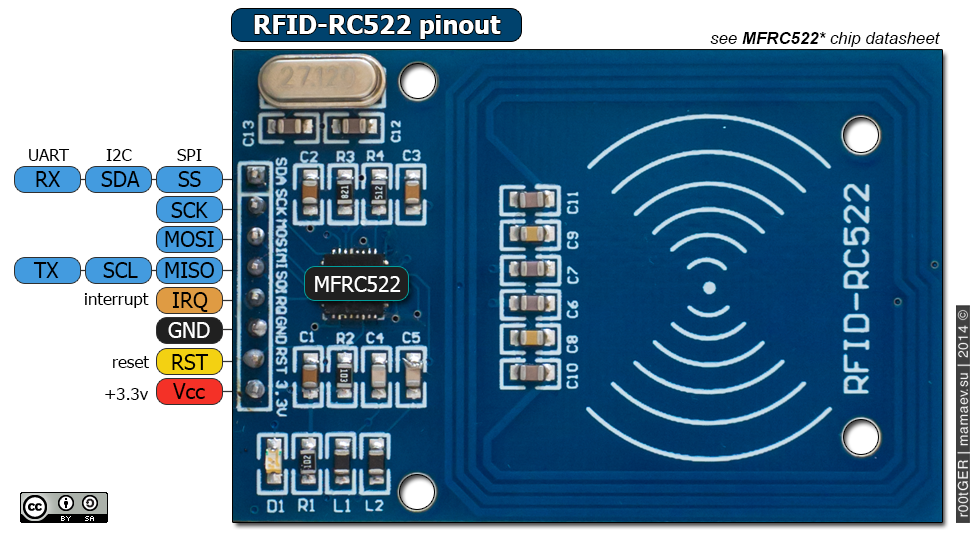
Pinout
The RFID-RC522 module has 8 pins, some pins are shared among three communication interfaces: SPI, I2C, UART. At a time, only one communication mode can be used. The pin are:
-
GND pin:connect this pin to GND (0V)
-
VCC pin: connect this pin to VCC (3.3V)
-
RST pin: is a pin for reset and power-down. When this pin goes low, hard power-down is enabled. On the rising edge, the module is reset.
-
MISO/SCL/TX pin: works as:
- - MISO pin if SPI interface is enabled
- - SCL pin if I2C interface is enabled
- - TX pin if UART interface is enabled.
-
MOSI pin: works as MOSI if SPI interface is enabled.
-
SCK pin:works as SCK if SPI interface is enabled
-
SS/SDA/RX pin: works as:
- SS pin if SPI interface is enabled
- SDA pin when I2C interface is enabled
- RX pin when UART interface is enabled.
※ NOTE THAT:
The RFID-RC522 module works with 3.3V. Do not connect the RFID-RC522 module's VCC pin to 5V. 5V can burn the RFID-RC522 module.
This tutorial uses SPI interface for communication between ESP32 and RFID-RC522 module.
Introduction to Relay
The relay is a programmable switch that can be used to control ON/OFF electrical devices. The relay can be programmatically controlled by ESP32 ⇒ ESP32 can control on/off the high voltage devices by using a relay.
※ NOTE THAT:
Safety first! Safety first!
Please be careful when working with high voltage. Seriously, it may shock you or even take your life. If you're NOT 100% sure what you are doing, do yourself a favor and don't touch anything. Ask someone who knows!
Some relays can work with both DC and AC voltage, we extremely recommend you NOT to use AC voltage. Use a DC device (≤24V) only.
Pinout

The relay pins can be categorized two groups: low voltage and high voltage.
The low voltage pins: are interfaced to ESP32, including three pins:
-
GND pin:connect this pin to GND (0V)
-
VCC pin: connect this pin to VCC (3.3V)
-
IN pin: is a pin for reset and power-down. When this pin goes low, hard power-down is enabled. On the rising edge, the module is reset.
The high voltage pins: are interfaced to high-voltage device, including three pins (usually in screw
-
NO pin: Normally Open pin
-
NC pin:Normally Closed pin
-
COM pin: the common pin
Normally, we do NOT use all high voltage pins. We usually use only two, depending on the operation mode we choose:
-
Normally open mode: Use only COM pin and NO pin
-
Normally closed mode:Use only COM pin and NC pin
※ NOTE THAT:
The pin order of the relay can be different between manufacturers. Please check the labels printed on the relay carefully!
How Relay Works
The relay has two operation modes:
- - Normally open mode
- - Normally closed mode.
Two modes works oppositely.
The “normally” means “if the IN pin is connected to LOW (0V)”.
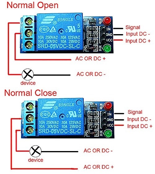
Normally Open Mode
Connect the high-voltage device to the COM pin and NO pin. Just like a switch:
-
If the IN pin is connected to LOW (0V), the switch is open. The device is OFF (or deactivated).
-
If the IN pin is connected to HIGH (5V or 3.3V), the switch is closed. The device is ON (or activated).
Normally Closed Mode
Connect the the high-voltage device to the COM pin and NC pin. Just like a switch:
-
If the IN pin is connected to LOW (0V) ⇒ The switch is closed ⇒ The device is ON (or activated).
-
If the IN pin is connected to HIGH (5V or 3.3V) ⇒ The switch is open ⇒ The device is OFF (or deactivated).
Wiring Diagram
Breadboard Connections

ESP32 Code
#include <SPI.h>
#include <MFRC522.h>

#define SS_PIN 5
#define RST_PIN 16
MFRC522 mfrc522(SS_PIN, RST_PIN);   // Create MFRC522 instance.

#define relayPin 4

void setup()
{
  Serial.begin(9600);   // Initiate a serial communication
  SPI.begin();      // Initiate  SPI bus
  mfrc522.PCD_Init();   // Initiate MFRC522
  Serial.println("Approximate your card to the reader...");
  Serial.println();

  pinMode(relayPin,OUTPUT);

}
void loop()
{
  // Look for new cards
  if ( ! mfrc522.PICC_IsNewCardPresent())
  {
    return;
  }
  // Select one of the cards
  if ( ! mfrc522.PICC_ReadCardSerial())
  {
    return;
  }
  //Show UID on serial monitor
  Serial.print("UID tag :");
  String content= "";
  byte letter;
  for (byte i = 0; i < mfrc522.uid.size; i++)
  {
     Serial.print(mfrc522.uid.uidByte[i] < 0x10 ? " 0" : " ");
     Serial.print(mfrc522.uid.uidByte[i], HEX);
     content.concat(String(mfrc522.uid.uidByte[i] < 0x10 ? " 0" : " "));
     content.concat(String(mfrc522.uid.uidByte[i], HEX));
  }
  Serial.println();
  Serial.print("Message : ");
  content.toUpperCase();
  if (content.substring(1) == "D2 E4 DA 1B") //change here the UID of the card/cards that you want to give access
  {
    Serial.println("Authorized access");
    Serial.println();
    digitalWrite(relayPin,HIGH);
    delay(2000);
    digitalWrite(relayPin,LOW);
  }

 else   {
    Serial.println(" Access denied");
    delay(1000);
  }
}
Quick Steps
- power up your board
- Open Arduino IDE
- Select the right board
- Select the right port
- Copy the above code and open with Arduino IDE
- Click Upload button on Arduino IDE to upload code to ESP32
- See the changes you made

Book Tutorial
We are considering to make the book tutorials. If you think the book tutorials are essential, you can download it. download book
See Also
References
※ NOTE THAT:
Some components works on 3.3v and others works on 5v!