
ESP32 - FADE LED
We are going to learn how to:
-
Fade LED using ESP32.
Video Tutorial
you can watch this video tutorial
Hardware Required
| 1 | × | ESP-WROOM-32 Dev Module | |
| 1 | × | Micro USB Cable | |
| 1 | × | LED | |
| 1 | × | 220 ohm resistor | |
| 1 | × | Breadboard | |
| 2 | × | Jumper Wires |
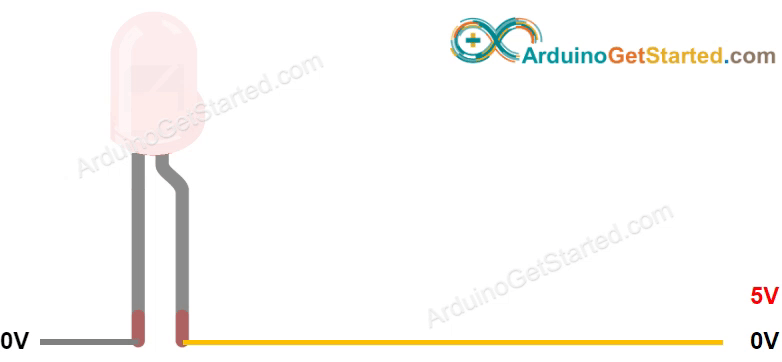
About LED
Pinout
LED includes two pins:
-
Cathode(-) pin needs to be connected to GND (0V)
-
Anode(+) pin is used to control LED's state
- If connecting GND to the anode(+), LED is OFF.
- If connecting VCC to the anode(+), LED is ON.
- If generating a PWM signal to the anode(+), the brightness of LED is changed according to PWM value. PWM value varies from 0 to 255. The bigger PWM value is, the brighter LED is. The smaller PWM value is, the darker LED is.
- If PWM value is 0, it is equivalent to GND, therefore, LED is OFF
- If PWM value is 255, it is equivalent to VCC, therefore, LED is fully ON
How It Works
After connecting the cathode(-) to GND:
※ NOTE THAT:
For most of LED, it needs to use a resistor between the anode(+) and VCC. The value of the resistor depends on the specification of LED.
ESP32 - fade LED
Some of ESP32 pins can be programmed to generate PWM signal. We can fade LED by connecting LED's anode(+) pin to an ESP32's pin, LED's cathode(-) to GND, and programming generate PWM on the ESP32's pin.
Wiring Diagram
Schematic Diagram

Image is developed using Fritzing. Click to enlarge image
Breadboard Connections

ESP32 Code
const byte led_gpio = 15;                  // the PWM pin the LED is attached to
int brightness = 0;                        // how bright the LED is

void setup() {
   ledcAttachPin(led_gpio, 0);             // assign a led pins to a channel
   ledcSetup(0, 4000, 8);                  // 4 kHz PWM, 8-bit resolution
}

void loop() {
   ledcWrite(0, brightness);               // set the brightness of the LED
   brightness++;                           // change the brightness for next time through the loop
   delay(10);                              // wait for 10 milliseconds to see the dimming effect
   if(brightness>255){                     // restart the fading at the ends of the fade
   brightness=0;
   }
}
※ NOTE THAT:
Becuase the esp32 does not support analogWrite() we used ledcWrite() instead.
Quick Steps
- power up your board
- Open Arduino IDE
- Select the right board
- Select the right port
- Copy the above code and open with Arduino IDE
- Click Upload button on Arduino IDE to upload code to ESP32
- Press and keep pressing the button several seconds
- See the changes you made

Code Explanation
Read the line-by-line explanation in comment lines of source code!
Book Tutorial
We are considering to make the book tutorials. If you think the book tutorials are essential, you can download it. download book
References
※ NOTE THAT:
Some components works on 3.3v and others works on 5v!