
ESP32 - Oled Buttons Status
This tutorial instructs you how to use ESP32 to . In detail:
-
How to use Buttons and OLED display with ESP32.
-
How to display Buttons status on OLED
Video Tutorial
you can watch this video tutorial
Hardware Required
| 1 | × | ESP-WROOM-32 Dev Module | |
| 1 | × | Micro USB Cable | |
| 1 | × | OLED Display | |
| 3 | × | Push Buttons | |
| 1 | × | Breadboard | |
| n | × | Jumper Wires |
About This Project
About OLED Display
please review our tutorial about OLED display here
About Buttons
please review our tutorial about Buttons here
Wiring Diagram
Schematic Diagram
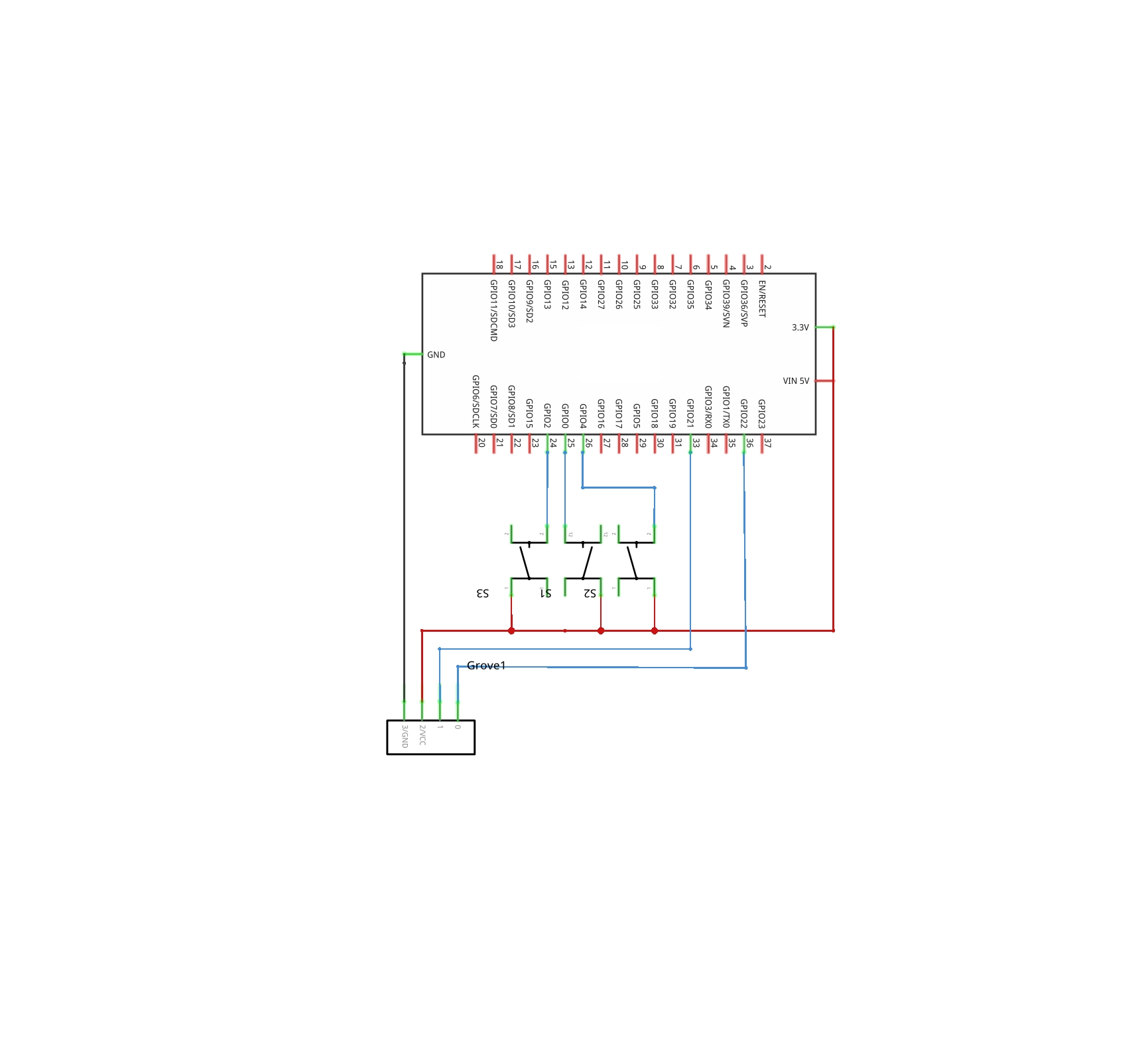
Image is developed using Fritzing. Click to enlarge image
Breadboard Connections

※ NOTE THAT:
The order of the OLED module's pins can vary between manufacturers. ALWAYS use the labels printed on the OLED module. Look closely!
In the above wiring diagram, you just need to use the male-to-female jumper wires. If you use the male-to-male jumper wires, you need to use breadboard in addition.
ESP32 Code
#include <Wire.h>
#include <Adafruit_GFX.h>
#include <Adafruit_SSD1306.h>

#define SCREEN_WIDTH 128 // OLED display width, in pixels
#define SCREEN_HEIGHT 64 // OLED display height, in pixels

#define OLED_RESET     -1 // Reset pin # (or -1 if sharing Arduino reset pin)
#define SCREEN_ADDRESS 0x3C //See datasheet for Address; 0x3D for 128x64, 0x3C for 128x32
Adafruit_SSD1306 display(SCREEN_WIDTH, SCREEN_HEIGHT, &Wire, OLED_RESET);

#define button1  15
#define button2  2
#define button3  4

int b1,b2,b3;     // variables to store


void setup() {
  Serial.begin(9600);

  pinMode(button1,INPUT_PULLUP);
  pinMode(button2,INPUT_PULLUP);
  pinMode(button3,INPUT_PULLUP);

  // SSD1306_SWITCHCAPVCC = generate display voltage from 3.3V internally
  if(!display.begin(SSD1306_SWITCHCAPVCC, SCREEN_ADDRESS)) {
    Serial.println(F("SSD1306 allocation failed"));
    for(;;); // Don't proceed, loop forever
  }

  // Show initial display buffer contents on the screen --
  // the library initializes this with an Adafruit splash screen.
  display.display();
  delay(2000); // Pause for 2 seconds

  display.clearDisplay();                 // clear display
  display.setTextSize(1);                 // set text size
  display.setTextColor(WHITE, BLACK);     // set text color

}

void loop() {

  if(digitalRead(button1) == HIGH){
    display.setCursor(5, 5);                     // set position to display
    display.println("button1 status : ON ");    // set text
    display.display();                         // display on OLED

  }
  else{
    display.setCursor(5, 5);
    display.println("button1 status : OFF");
    display.display();
  }

  if(digitalRead(button2) == HIGH){
    display.setCursor(5, 30);
    display.println("button2 status : ON ");
    display.display();
  }
  else{
    display.setCursor(5, 30);
    display.println("button2 status : OFF");
    display.display();
  }

  if(digitalRead(button3) == HIGH){
    display.setCursor(5, 55);
    display.println("button3 status : ON ");
    display.display();
  }
  else{
    display.setCursor(5, 55);
    display.println("button3 status : OFF");
    display.display();
  }

}
Quick Steps
- power up your board
- Open Arduino IDE
- Select the right board
- Select the right port
- Copy the above code and open with Arduino IDE
- Click Upload button on Arduino IDE to upload code to ESP32
- Press and keep pressing the button several seconds
- See the changes you made

Book Tutorial
We are considering to make the book tutorials. If you think the book tutorials are essential, you can download it. download book
See Also
References
※ NOTE THAT:
Some components works on 3.3v and others works on 5v!