
ESP32 - BLINK LED
We are going to learn how to:
-
Blink LED using ESP32.
Video Tutorial
you can watch this video tutorial
Hardware Required
| 1 | × | ESP-WROOM-32 Dev Module | |
| 1 | × | Micro USB Cable | |
| 1 | × | LED | |
| 1 | × | 220 ohm resistor | |
| 1 | × | Breadboard | |
| 2 | × | Jumper Wires |
About LED
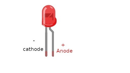
Pinout
LED includes two pins:
-
Cathode(-) pin needs to be connected to GND (0V)
-
Anode(+) pin is used to control LED's state
How It Works
After connecting the cathode(-) to GND:
-
If connecting GND to the anode(+), LED is OFF.
-
If connecting VCC to the anode(+), LED is ON.

Besides, if generating a PWM signal to the anode(+), the brightness of LED is changed according to PWM value ( described in detail in this tutorial)
※ NOTE THAT:
For most of LED, it needs to use a resistor between the anode(+) and VCC. The value of the resistor depends on the specification of LED.
Wiring Diagram
Schematic Diagram

Image is developed using Fritzing. Click to enlarge image
Breadboard Connections

ESP32 Code
void setup() {                  // the setup function runs once when you press reset or power the board
    pinMode(15, OUTPUT);        // initialize digital pin GIOP18 as an output.
}
void loop() {                   // the loop function runs over and over again forever
    digitalWrite(15, HIGH);     // turn the LED on (HIGH is the voltage level)
    delay(1000);                // wait for 1000 milliseconds
    digitalWrite(15, LOW);      // turn the LED off by making the voltage LOW
    delay(1000);                // wait for 1000 milliseconds
}
Quick Steps
- power up your board
- Open Arduino IDE
- Select the right board
- Select the right port
- Copy the above code and open with Arduino IDE
- Click Upload button on Arduino IDE to upload code to ESP32
- Press and keep pressing the button several seconds
- See the changes you made

Code Explanation
-
configure an ESP32's pin to digital output mode by using pinMode() function.
-
program the pin to GND to turn off led by using digitalWrite(pinNumber,LOW)
-
program the pin to VCC to turn on led by using digitalWrite(pinNumber,HIGH)
Read the line-by-line explanation in comment lines of source code!
※ NOTE THAT:
The above code uses the delay(). This function blocks ESP32 from doing other tasks during the delay time. If your project requires to do some tasks, avoid blocking ESP32 by using the non-blocking method for ESP32.
Book Tutorial
We are considering to make the book tutorials. If you think the book tutorials are essential, you can download it. download book
References
※ NOTE THAT:
Some components works on 3.3v and others works on 5v!