
ESP32 - CAM - Face Detection
This tutorial instructs you
-
how to setup a video streaming web server with face recognition and detection
Video Tutorial
you can watch this video tutorial
Hardware Required
| 1 | × | ESP32-CAM with OV2640 | |
| 1 | × | USP to TTL | |
| 1 | × | Breadboard | |
| n | × | Jumper Wires |
Introduction to ESP32-CAM
The ESP32-CAM is a very small camera module with the ESP32-S chip. Besides the OV2640 camera, and several GPIOs to connect peripherals, it also features a microSD card slot that can be useful to store images taken with the camera or to store files to serve to clients.

The ESP32-CAM doesn't come with a USB connector, so you need an FTDI programmer or USPtoTTL to upload code through the U0R and U0T pins (serial pins).
ESP32-CAM Pinout
The following figure shows the ESP32-CAM pinout (AI-Thinker module).

-
There are three GND pins and two pins for power: either 3.3V or 5V.
-
GPIO 1 and GPIO 3 are the serial pins. You need these pins to upload code to your board.
-
GPIO 0 also plays an important role, since it determines whether the ESP32 is in flashing mode or not. When GPIO 0 is connected to GND, the ESP32 is in flashing mode.
-
The following pins are internally connected to the microSD card reader:
- GPIO 14: CLK
- GPIO 15: CMD
- GPIO 2: Data 0
- GPIO 4: Data 1 (also connected to the on-board LED)
- GPIO 12: Data 2
- GPIO 13: Data 3
Video Streaming Server
Follow the next steps to build a video streaming web server with the ESP32-CAM that you can access on your local network.
※ NOTE THAT:
Make sure you have your Arduino IDE updated as well as the latest version of the ESP32 add-on.
CameraWebServer Example Code
In your Arduino IDE, go to File > Examples > ESP32 > Camera and open the CameraWebServer example.

The following code should load.

Before uploading the code, you need to insert your network credentials in the following variables:
const char* ssid = "REPLACE_WITH_YOUR_SSID";
const char* password = "REPLACE_WITH_YOUR_PASSWORD";
Then, make sure you select the right camera module. In this case, we're using the AI-THINKER Model.
So, comment all the other models and uncomment this one:
// Select camera model
//#define CAMERA_MODEL_WROVER_KIT
//#define CAMERA_MODEL_ESP_EYE
//#define CAMERA_MODEL_M5STACK_PSRAM
//#define CAMERA_MODEL_M5STACK_WIDE
#define CAMERA_MODEL_AI_THINKER
If none of these correspond to the camera you're using, you need to add the pin assignment for your specific board in the camera_pins.h tab.
Now, the code is ready to be uploaded to your ESP32.
ESP32-CAM Upload Code
Connect the ESP32-CAM board to your computer using an FTDI programmer or USPtoTTL. Follow the next schematic diagram:

Many FTDI programmers and USPtoTTL have a jumper that allows you to select 3.3V or 5V. Make sure the jumper is in the right place to select 5V.
※ NOTE THAT:
GPIO_0 needs to be connected to GND so that you're able to upload code.
| ESP32-CAM | USPtoTTL |
| GND | GND |
| 5V | VCC (5V) |
| U0R | TX |
| U0T | RX |
| GPIO_0 | GND |
To upload the code, follow the next steps:
- Open Arduino IDE
- Select the right board
- Select the right port
- Copy the above code and open with Arduino IDE
- Click Upload button on Arduino IDE to upload code to ESP32
- When you start to see these dots on the debugging window as shown below, press the ESP32-CAM on-board RST button.s


After a few seconds, the code should be successfully uploaded to your board.
Getting the IP address
After uploading the code, disconnect GPIO 0 from GND.
Open the Serial Monitor at a baud rate of 115200. Press the ESP32-CAM on-board Reset button.
The ESP32 IP address should be printed in the Serial Monitor.

Accessing the Video Streaming Server
Now, you can access your camera streaming server on your local network. Open a browser and type the ESP32-CAM IP address. Press the Start Streaming button to start video streaming.
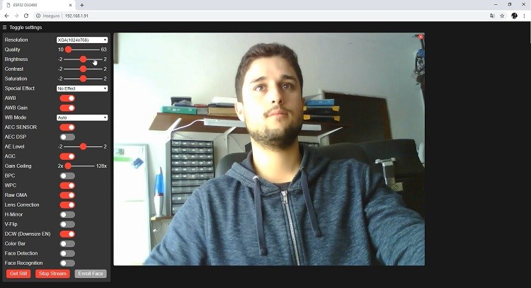
You also have the option to take photos by clicking the Get Still button. Unfortunately, this example doesn't save the photos, but you can modify it to use the on board microSD Card to store the captured photos.
There are also several camera settings that you can play with to adjust the image settings.
Finally, you can do face recognition and detection.

First, you need to enroll a new face. It will make several attempts to save the face. After enrolling a new user, it should detect the face later on (subject 0).

And that's it. Now you have your video streaming web server up and running with face detection and recognition with the example from the library.
Book Tutorial
We are considering to make the book tutorials. If you think the book tutorials are essential, you can download it. download book
See Also
References
※ NOTE THAT:
Some components works on 3.3v and others works on 5v!